Link Ads

More search type here...

January 19, 2023

Arduino circuit for digital clock and Coding

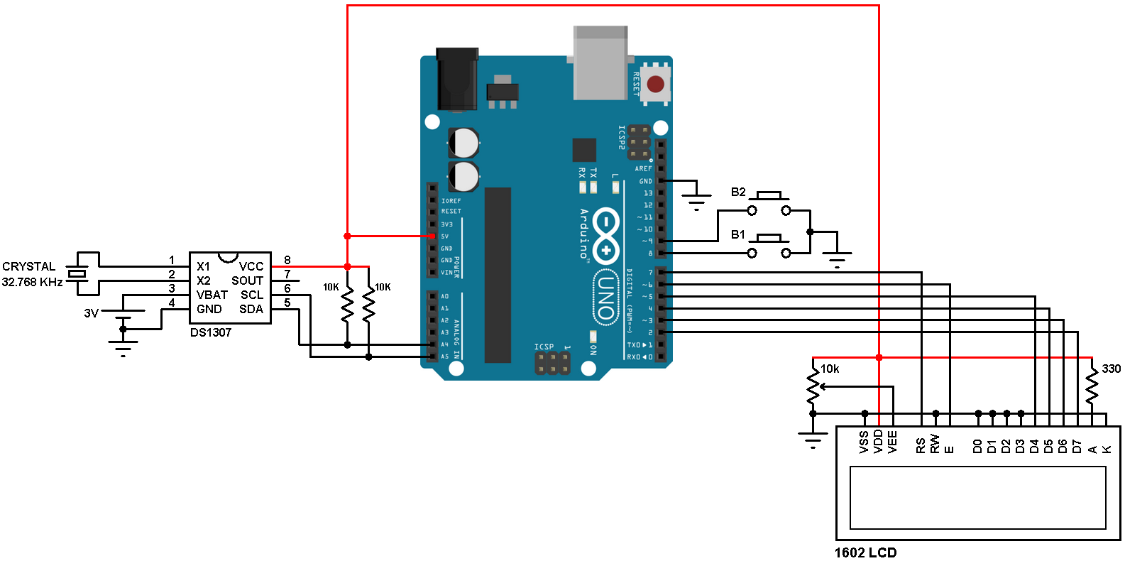
An Arduino circuit for a digital clock can be created using an Arduino board, a 16x2 LCD display, a real-time clock module, and a few passive components such as resistors and a capacitor. The real-time clock module, such as the DS1307, provides the timekeeping functionality, while the LCD display is used to display the current time. The Arduino board is used to control the LCD and interface with the real-time clock module. A simple circuit diagram could be:


Arduino ------------------------- LCD
|
|
R1,R2
|
|
DS1307


Arduino oding for clock display
Here is an example of Arduino code for displaying the current time on an LCD using a real-time clock module:

Copy code
#include <Wire.h>
#include <LiquidCrystal_I2C.h>
#include <RTClib.h>

RTC_DS1307 rtc;
LiquidCrystal_I2C lcd(0x27, 16, 2);

void setup() {
  lcd.begin();
  lcd.backlight();
  rtc.begin();
  if (!rtc.isrunning()) {
    lcd.print("RTC is NOT running!");
    // following line sets the RTC to the date & time this sketch was compiled
    rtc.adjust(DateTime(F(__DATE__), F(__TIME__)));
  }
}

void loop() {
  DateTime now = rtc.now();
  lcd.setCursor(0, 0);
  lcd.print(now.hour(), DEC);
  lcd.print(':');
  lcd.print(now.minute(), DEC);
  lcd.print(':');
  lcd.print(now.second(), DEC);
  lcd.setCursor(0, 1);
  lcd.print(now.day(), DEC);
  lcd.print('/');
  lcd.print(now.month(), DEC);
  lcd.print('/');
  lcd.print(now.year(), DEC);
  delay(1000);
}
 

This code uses the Wire and RTClib libraries to interface with the real-time clock module. The LiquidCrystal_I2C library is used to control the LCD display. The code first checks if the real-time clock is running, and sets the time if it is not. Then, in the loop, it continuously updates the LCD display with the current time and date retrieved from the real-time clock.

Note: in the code above, you can see that the I2C address of the LCD is 0x27, if it's different for you, you need to change that to the correct one.


KALMAN FILTER IN ARDUINO without Header file kalman.h

This is a basic Kalman filter that uses a constant measurement noise and process noise. You can adjust these values to fine-tune the filter for your specific application. The filter takes a measurement (z_measured) and uses it to estimate the real value (z_real). The estimated value is then updated with each new measurement.

#define MEASUREMENT_NOISE 0.1
#define PROCESS_NOISE 0.05

double x_est_last = 0;
double P_last = 0;
double K;
double P;
double x_temp_est;
double x_est;
double z_measured = 0; // the measured value
double z_real = 0; // the real value

void KalmanFilter()
{
    x_temp_est = x_est_last;
    P = P_last + PROCESS_NOISE;
    K = P / (P + MEASUREMENT_NOISE);
    x_est = x_temp_est + K * (z_measured - x_temp_est);
    P = (1 - K) * P;
    x_est_last = x_est;
    P_last = P;
}


January 17, 2023

Arduino Code for Kalman Filter


The Kalman filter is a mathematical algorithm that uses a series of measurements observed over time, containing noise (random variations) and other inaccuracies, and produces estimates of unknown variables that tend to be more accurate than those based on a single measurement alone. It is used in a wide range of applications, including signal processing, control systems, and navigation.

The filter is named after its inventor, Rudolf Kalman, who first described it in a paper published in 1960. It is based on a series of mathematical equations that describe how the variables of interest (such as the position and velocity of an object) evolve over time, and how these variables are related to the measurements that are being made. The filter uses these equations to estimate the values of the variables based on the measurements, and then updates these estimates as new measurements become available.

The Kalman filter is particularly useful in systems where the variables of interest are subject to random variations (noise) and other inaccuracies, and where the measurements are also subject to similar errors. The filter is able to take into account the uncertainty in the measurements and the system dynamics, and produce estimates that are optimal in some sense (e.g., minimum variance).

Case Study

The LM35 is a precision temperature sensor that can be used to measure temperature in degrees Celsius. It can be used in conjunction with a Kalman filter to filter out noise and provide a more accurate temperature reading. Here is an example circuit for using an LM35 with a Kalman filter on an Arduino:

#include <Kalman.h>

Kalman kalman;
int lm35Pin = A0; // The pin the LM35 is connected to
double temperature;
double filteredTemperature;

void setup() {
  Serial.begin(9600);
  kalman.setMeasurementNoise(0.1); // Set the measurement noise variance
  kalman.setProcessNoise(0.01); // Set the process noise variance
}

void loop() {
  temperature = analogRead(lm35Pin) * 0.48828125; // Read the LM35 and convert to degrees Celsius
  filteredTemperature = kalman.updateEstimate(temperature); // Update the filtered temperature estimate
 

  Serial.print("Temperature: ");
  Serial.print(temperature);
  Serial.print("\tFiltered Temperature: ");
  Serial.println(filteredTemperature);
 
  delay(100);
}

In this example, the LM35 is connected to pin A0 on the Arduino, and the analogRead() function is used to read the voltage output of the LM35. The voltage is then converted to temperature in degrees Celsius using the LM35's voltage-to-temperature conversion factor.

The Kalman filter is used to filter out noise in the temperature measurement by updating the estimate of the temperature with the new measurement and the previous estimate.

You should adjust the measurement noise and process noise variance to match your system's characteristics and specific requirements.

It's important to note that the example code is for illustrative purposes only and may need to be modified to work with your specific hardware and application.


Here another Example Code

===========================================================

#include <Kalman.h>

Kalman kalmanX; // Create Kalman filter objects
Kalman kalmanY;

double x = 0; // Set initial values
double y = 0;
double dx, dy;

void setup() {
  Serial.begin(9600);

  // Set the measurement noise variance for each filter
  kalmanX.setMeasurementNoise(1);
  kalmanY.setMeasurementNoise(1);

  // Set the process noise variance for each filter
  kalmanX.setProcessNoise(0.01);
  kalmanY.setProcessNoise(0.01);
}

void loop() {
  x = kalmanX.updateEstimate(x + dx); // Update the estimate for x
  y = kalmanY.updateEstimate(y + dy); // Update the estimate for y

  Serial.print("X: ");
  Serial.print(x);
  Serial.print("\tY: ");
  Serial.println(y);

  delay(100);
}