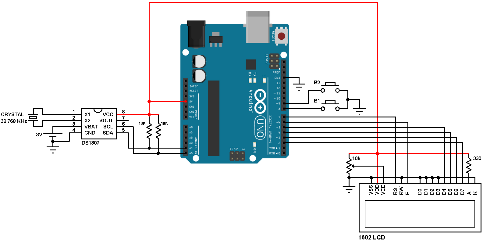
An Arduino circuit for a digital clock can be created using an Arduino board, a 16x2 LCD display, a real-time clock module, and a few passive components such as resistors and a capacitor. The real-time clock module, such as the DS1307, provides the timekeeping functionality, while the LCD display is used to display the current time. The Arduino board is used to control the LCD and interface with the real-time clock module. A simple circuit diagram could be:
Arduino ------------------------- LCD
|
|
R1,R2
|
|
DS1307
Arduino oding for clock display
Here is an example of Arduino code for displaying the current time on an LCD using a real-time clock module:
Copy code
#include <Wire.h>
#include <LiquidCrystal_I2C.h>
#include <RTClib.h>
RTC_DS1307 rtc;
LiquidCrystal_I2C lcd(0x27, 16, 2);
void setup() {
lcd.begin();
lcd.backlight();
rtc.begin();
if (!rtc.isrunning()) {
lcd.print("RTC is NOT running!");
// following line sets the RTC to the date & time this sketch was compiled
rtc.adjust(DateTime(F(__DATE__), F(__TIME__)));
}
}
void loop() {
DateTime now = rtc.now();
lcd.setCursor(0, 0);
lcd.print(now.hour(), DEC);
lcd.print(':');
lcd.print(now.minute(), DEC);
lcd.print(':');
lcd.print(now.second(), DEC);
lcd.setCursor(0, 1);
lcd.print(now.day(), DEC);
lcd.print('/');
lcd.print(now.month(), DEC);
lcd.print('/');
lcd.print(now.year(), DEC);
delay(1000);
}
This code uses the Wire and RTClib libraries to interface with the real-time clock module. The LiquidCrystal_I2C library is used to control the LCD display. The code first checks if the real-time clock is running, and sets the time if it is not. Then, in the loop, it continuously updates the LCD display with the current time and date retrieved from the real-time clock.
Note: in the code above, you can see that the I2C address of the LCD is 0x27, if it's different for you, you need to change that to the correct one.
